Direct answer
Choose a YIG-tuned oscillator when one source must cover an octave or more and stay clean across that band. Choose a varactor-tuned VCO when the frequency must hop in microseconds, or when the package and coil power of a YIG source will not fit. Choose a DRO when the frequency is essentially fixed and close-in phase noise is the parameter that binds. They are not grades of the same part: each wins one constraint and loses the others, and a better driver will not convert one architecture into another.
Key takeaways
- The decision is range versus speed versus close-in purity — pick the constraint that binds first.
- A YIG source is a current-tuned magnet; a VCO is a voltage-tuned varactor; a DRO is a geometry-tuned puck.
- Headline phase noise without an offset and a carrier is not a comparison.
- If the frequency plan is fixed, a YIG oscillator is usually the expensive way to buy a DRO.
- Microsecond hops across a band rule a YIG source out, regardless of its spectral purity.
The three common microwave sources are asked to do the same job — put a clean tone on a frequency — and they do it by three different mechanisms. That is why a datasheet bake-off without a constraint is meaningless. This page is the decision. The device-level specification of a YIG-tuned oscillator lives in the component guide; the material and the loop are in the YIG technology section.
The conclusion, before the table
If the LO must tune an octave or more and stay spectrally clean, it is a YIG-tuned oscillator. That is the default in broadband test equipment and wideband receivers, and it has been for decades, because no other resonator follows a field linearly across that span.
If the frequency must move in microseconds, or the box cannot spend watts holding a coil current, it is a VCO. Wideband VCOs pay for that agility in phase noise and in a non-linear tuning curve. That trade is acceptable in agile synthesis and in PLL blocks where the loop will clean the close-in region.
If the frequency is fixed and close-in purity is the binding number, it is a DRO. A high-Q dielectric puck at one frequency, often locked to a crystal or OCXO, is quieter close-in than a wideband fundamental source and quieter far-out than a multiplied chain of the same convenience.
How they actually tune
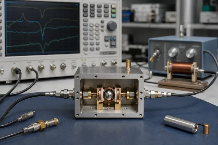
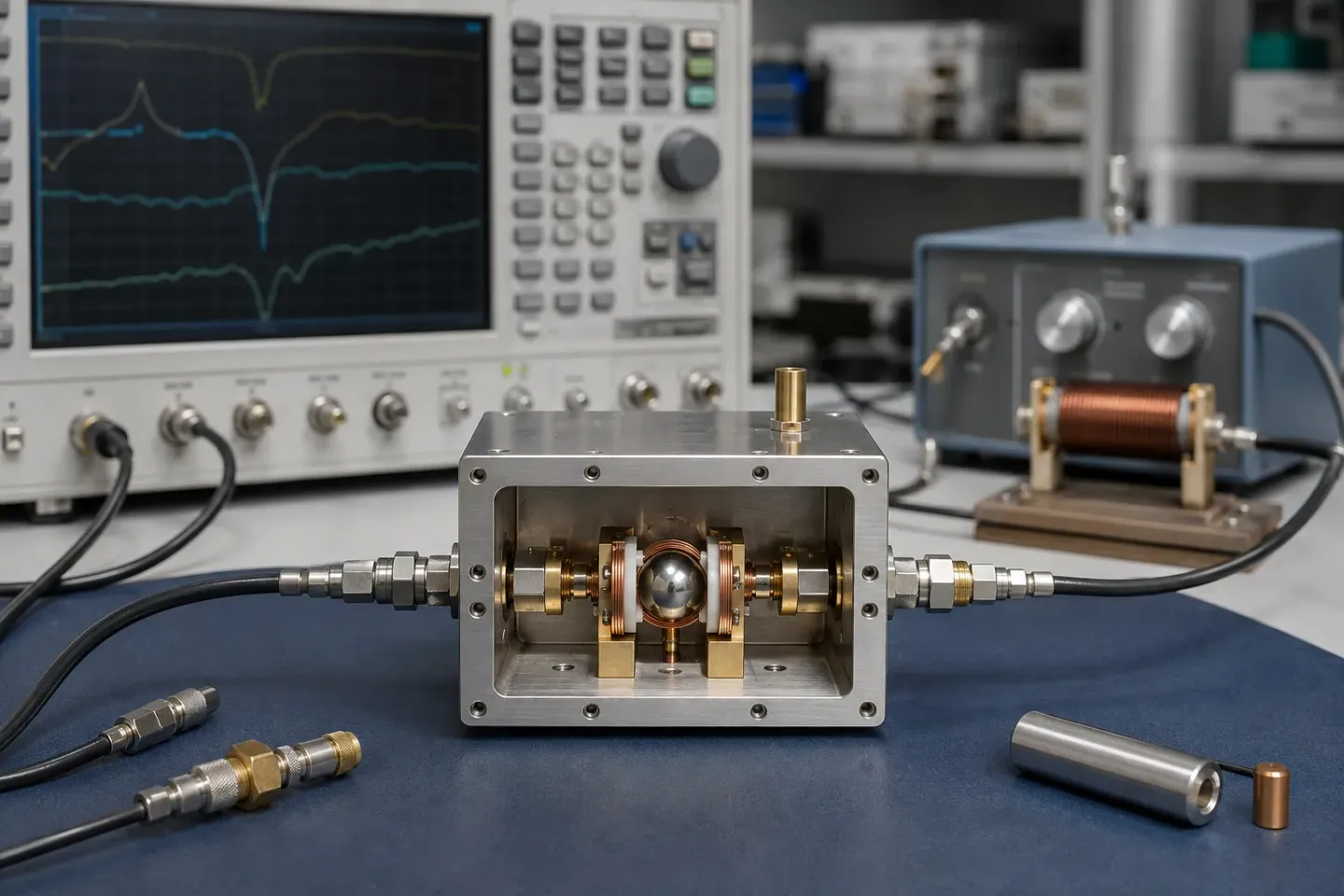
A YIG-tuned oscillator locks a negative-resistance device to a sphere whose resonance follows an applied magnetic field. The control variable is coil current. The main coil covers the band and settles in milliseconds; the FM coil covers a narrow span fast enough to sit inside a loop.
A varactor-tuned VCO moves frequency by changing the capacitance of a junction. The control variable is voltage. The resonator Q is lower, the tuning curve is non-linear, and hop time is set by the varactor and the loop, not by an electromagnet — which is why VCOs hop in well under a microsecond.
A DRO sets frequency by the size and permittivity of a dielectric puck. The control variable is geometry, with at most a narrow varactor or a mechanical screw around that point. There is no octave of electrical tuning to discuss. What you buy is unloaded Q at one frequency.
Those three sentences are the whole comparison. Everything in the table below is a consequence of them.
Side by side
| Criterion | YIG-tuned oscillator | Varactor-tuned VCO | Dielectric resonator oscillator |
|---|---|---|---|
| What sets frequency | Magnetic field on a YIG sphere | Varactor capacitance | Puck geometry |
| Control variable | Coil current | Tuning voltage | Almost none; optional trim |
| Tuning range | Octave or more from one device | Wide, typically less than a YTO, non-linear | Essentially fixed |
| Settling / hop time | Milliseconds on the main coil | Sub-microsecond | Not a hop; lock time only |
| Phase noise, wide tune | Low across the band; fundamental | Worse, and worse as the band widens | Not applicable |
| Phase noise, fixed frequency | Good, rarely the quietest close-in | Depends on resonator Q and lock | Best close-in of the three |
| Tuning linearity | Very linear in current | Markedly non-linear in voltage | Not applicable |
| Standby power | Continuous coil current | Low | Low |
| Size | Large; the magnet dominates | Small, often a single package | Small |
| Magnetic sensitivity | Significant — the field is the control | Negligible | Negligible |
| Typical role | Wideband LO, sweeper | Agile synthesis, PLL block | Fixed low-noise reference or LO |
Commercial electromagnet YTOs collectively cover roughly 700 MHz to 40 GHz across models, with millisecond-class main-coil settling and continuous coil power. That envelope is the shape of the class, not a specification for a part you might buy.
Phase noise is not one number
A comparison that quotes one dBc/Hz figure for each architecture is already finished, and finished wrongly. Phase noise is a curve, and the offset your system integrates over is part of the answer.
- A receiver fighting a strong neighbour cares about mid-range offsets, where reciprocal mixing lives.
- A coherent radar or a frequency measurement cares close-in.
- A wideband downconverter often cares about the far-out floor, because that floor sets noise figure.
A YTO’s advantage on a wide tune is that it is a fundamental oscillator. A multiplied VCO chain pays 20·log₁₀(N) before the multiplier adds its own noise, which is why a YTO that looks unremarkable on a headline can still be the quieter option at frequency. A DRO’s advantage is the opposite situation: one frequency, high resonator Q, and — when locked — the reference’s close-in noise on top of the puck’s far-out floor.
If you cannot say which offset band matters, you cannot yet choose among these three.
Cost, integration and what “driver” means
A VCO is typically a component. A DRO is typically a component, sometimes sold already locked. A YTO is a control system: oscillator plus current driver plus calibration. Buying the sphere assembly without the driver transfers current accuracy, driver noise and thermal correction to you, and the datasheet phase noise figure no longer describes what you built.
That integration cost is why a YTO loses on programmes that do not need its range. It is also why “we already have a VCO vendor” is not a technical argument against a YTO — the parts do not substitute.
What to pick, by job
- Spectrum or signal analyser LO, wideband EW receiver, ATE sweeper. YTO. Coverage and sweep linearity bind first; millisecond settling is already in the instrument’s time budget.
- Agile synthesizer, fast-hop radio, on-board PLL. VCO. Hop time binds first. Spend the phase-noise budget on the loop and the reference, not on a magnet.
- Fixed LO, sample clock, microwave link, quiet reference. DRO. Close-in purity binds first. If Analog Devices needed a DRO to stop a clock from wasting a DAC’s residual noise, your fixed LO is not a more relaxed case.
- Radar. It depends on the waveform, which is a real split rather than a hedge. A hopping or wideband LO is a YTO; a fixed-channel or pulsed-on-frequency LO is usually a DRO. See radar RF components.
A YIG-tuned preselector next to a YTO is a common pairing in monitoring and EW front ends. Both settle slowly. Budget them together.
The last question is procurement, not RF, and it still decides programmes. The general version is in sourcing and quality. For how the YIG mechanism produces the range you are buying, start with what YIG is.
Decide the architecture before reading headline specifications
Start by classifying the frequency requirement. A source that must cover a continuous multi-octave band is a different problem from one that visits six channels, even if their lowest and highest frequencies match. A source that must move in microseconds is a different problem from one that may settle for milliseconds. A source whose close-in phase noise limits coherent processing is different from one whose far-out noise limits a wideband converter. These statements narrow the architecture before a single phase-noise plot or tuning-range number is compared.
Next identify the control boundary. A VCO commonly expects to sit inside a loop you control. A DRO may be used free-running or in a narrow correction loop. A YTO is often bought as a source plus driver and sometimes as part of a synthesised assembly. The responsibility for reference quality, loop stability, current noise, calibration and tuning direction changes with that boundary. Comparing a bare VCO to a fully calibrated YTO module without including those surrounding functions is a comparison of different systems.
Make phase noise contextual. Write the carrier frequencies, the offsets that matter, the integration band and the lock condition. At close offsets, reference and loop design may dominate; at larger offsets, oscillator noise or an output amplifier can dominate. A DRO can win strongly in a fixed quiet application, while a YTO can earn its added complexity by covering a band no fixed resonator can span. The phase-noise guide gives a way to turn that statement into named limits.
Finally, compare the operating burden. Include size, coil or loop power, magnetic clearance, warm-up, calibration storage, reference distribution, availability and repair repeatability. For a long-life programme, the part number is not enough: you need the data and test conditions that let a replacement preserve behaviour. This is particularly important for YIG sources, where the oscillator integration guide explains why driver and magnetic history remain part of the RF result.
The output of this exercise should be a short architecture choice with exceptions, not a universal winner: choose YTO for continuous coverage when its settling fits; choose VCO for fast agility when its noise can be budgeted; choose DRO for fixed-frequency purity when coverage is not the constraint.
Frequently asked questions
Can a PLL make a VCO as clean as a DRO?
It can borrow the reference's close-in noise inside the loop bandwidth. Outside that bandwidth the oscillator's own floor remains, and a typical wideband VCO is still noisier than a high-Q dielectric resonator. The loop does not erase the resonator.
Can I hop a YIG oscillator fast enough for an agile radar?
Not across the band. Main-coil steps settle in milliseconds because the coil is inductive. The FM coil is fast, but only over a narrow correction around wherever the main coil has parked. If the hop itself must be microseconds and wide, the architecture is wrong.
Is a YIG oscillator always quieter than a VCO?
Across a wide tuning range, usually yes — and it avoids the 20·log₁₀(N) penalty of a multiplied chain. At one fixed frequency a DRO is typically quieter close-in, and a narrowband VCO can be close enough that size and cost decide.
Do I ever combine them?
Yes. A common plan uses a DRO or a clean VCO as a fixed reference or clock, and a YIG source as the wideband LO. The comparison is which block plays which role, not which vendor to standardise on.
Sources
- Electromagnetic YIG Oscillators (Wide Tuning Range) — Micro Lambda Wireless Accessed August 28, 2026.
- Phase Noise Measurements with a Real-Time Spectrum Analyzer, chapter 7 — Berkeley Nucleonics Accessed August 28, 2026.