Direct answer
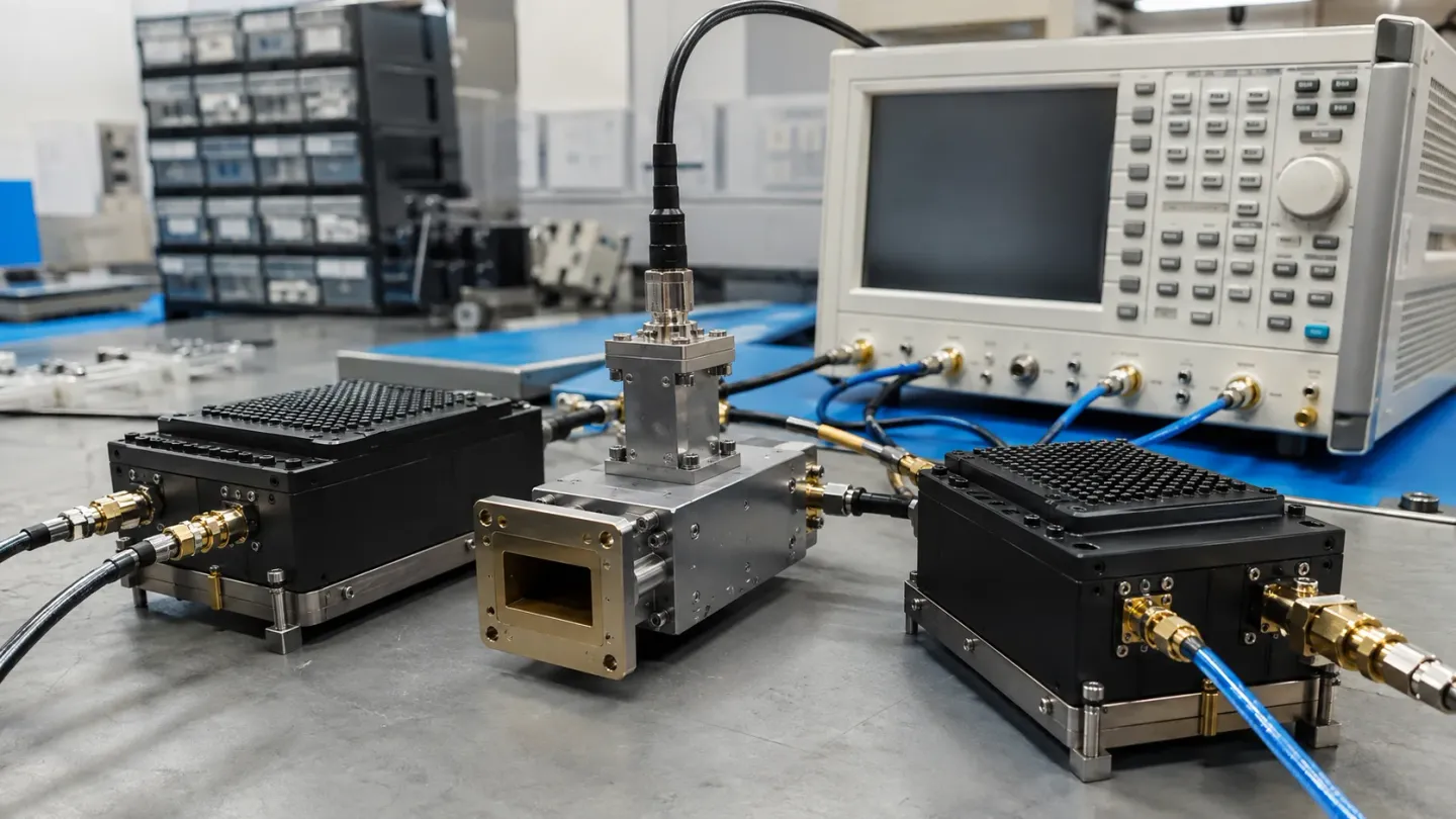
A radar front end is a receiver and usually an exciter sharing one frequency plan. The waveform decides the components. If the LO must tune an octave or hop from pulse to pulse across a wide band, the source is a YIG-tuned oscillator and the preselector, if you have one, is a YIG filter — and their millisecond settling has to fit the timeline. If the radar sits on a known channel and close-in purity binds, the LO is a DRO or a locked narrow source and the RF filters are cavities. Phase noise is judged at the offsets the waveform integrates over, not at a datasheet marker.
Key takeaways
- Write the waveform’s time and offset-frequency budget before you pick a source family.
- Wideband or hopping LOs are YIG problems; fixed-channel LOs are DRO problems.
- A tracking preselector and a YTO settle in the same budget — add them.
- Reciprocal mixing, not headline dBc/Hz, is why the LO and the preselector exist.
- Transmit power handling and receive limiting are different filter purchases.
“Radar RF components” is not a catalogue. It is a frequency plan with a timeline attached. The same mixer, filter and oscillator families that show up in test equipment show up here; the waveform decides which constraint binds first. This page is the mapping. It sits in applications, where the binding constraint comes from the mission rather than from the part; the device pages live under components and YIG technology, and the frequency-plan identities live in the signal chain section.
The front end as a constraint chain
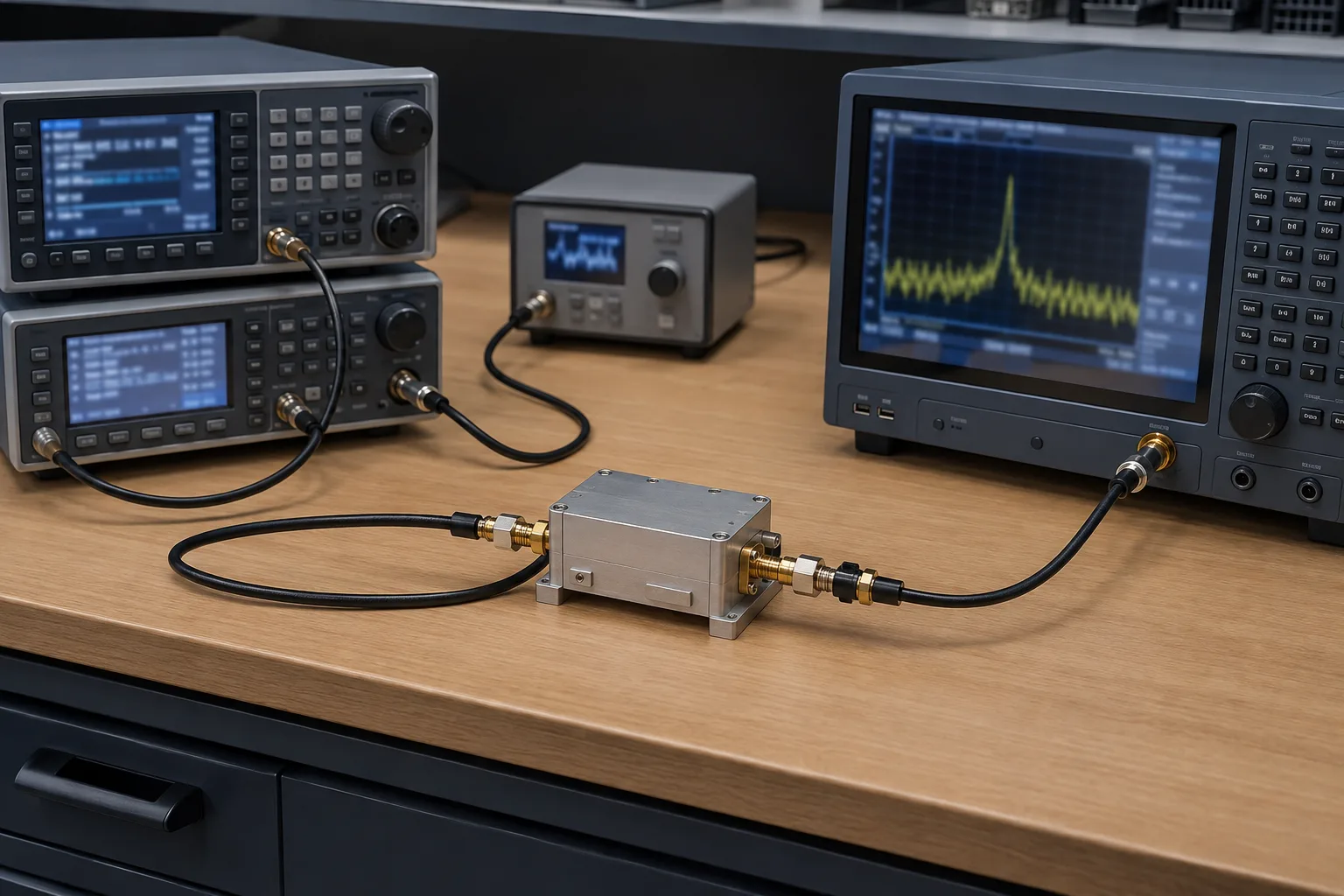
A typical receive path is antenna → limiter → LNA → preselector → mixer ← LO → IF. A typical exciter path is the reverse translation: IF or a clean reference, upconverted to the radiating RF. Downconversion and upconversion are those two directions. They often share the LO.
Three numbers then decide the parts:
- How far the RF must move, and how fast.
- Which offset frequencies the waveform integrates — Doppler, clutter, a jammer, the image.
- How much power sits on the transmit path and how much can arrive at the receive path.
Write those down before you open a datasheet. The rest of this page is those three numbers mapped onto device classes.
The LO: range, speed, purity
| Waveform constraint | What binds | Usual source |
|---|---|---|
| Multi-octave coverage, sweep or search | Tuning range and linearity | YIG-tuned oscillator |
| Pulse-to-pulse hop across a wide band, microsecond class | Hop time | VCO / fast synthesizer — not YIG |
| Pulse-to-pulse hop across a wide band, millisecond class | Hop time still fits a coil | YIG-tuned oscillator |
| Fixed channel, long coherent dwell, Doppler | Close-in phase noise | DRO, often locked |
| Wide instantaneous bandwidth | Far-out floor, not the close-in number | Quiet fundamental source; watch multiplied chains |
Class-level mapping. A locked assembly can move a row — a quiet reference inside the loop bandwidth, the oscillator’s own floor outside it.
The comparison behind that table is YIG oscillator vs VCO vs DRO. A YTO is still the default wideband microwave LO because it is a fundamental, linearly tuned source across an octave; commercial electromagnet parts collectively cover roughly 700 MHz to 40 GHz. It is the wrong default when the hop is faster than the main coil, or when the frequency never moves.
Close-in purity on a fixed channel is a DRO problem, for the same reason a high-performance clock uses a dielectric resonator rather than a wide-tuning MMIC VCO: the resonator Q is the specification, not the tuning range on the front of the brick.
Phase noise is a radar specification
L(f) without an offset is not a number. In radar the offset is chosen by the waveform:
- Close-in (below ~1 kHz, sometimes lower) sets how long you can integrate coherently and how fine a Doppler bin you can believe.
- Mid-range is where a strong nearby return or a jammer reciprocal-mixes into the IF. A tracking preselector is aimed at this as much as at the classical image.
- Far-out sets the noise that a wide chirp or a wide digital IF will integrate.
A YTO that looks average at 1 kHz and quiet at 100 kHz can be the right search-radar LO and the wrong instrumentation-radar LO. The datasheet marker will not tell you which you are building.
The preselector: move it, or machine it
If the LO walks, the image walks. The image is 2 × IF from the wanted RF, and after the mixer it is too late. A tracking YIG filter is the part that can walk with the LO and still present tens of megahertz of absolute width. A cavity is the part you want when the RF does not walk: lower loss, far higher power handling, no coil.
Two radar-specific catches:
Settling adds. A YTO and a YIG preselector are both electromagnets. A hop that settles in 2 ms on the oscillator and 2 ms on the filter is a 4 ms hop if you wait for both, unless the drivers are sequenced with a measured overlap. Search-radar timelines absorb that. Pulse-to-pulse agility often does not.
Limiting is not protection. Sphere limiting around 0 to +10 dBm means a large return can collapse the preselector. The limiter in front of the LNA is what protects the first transistor. Putting a YIG filter after the LNA still leaves the LNA exposed, and then asks the sphere to stay linear on whatever the LNA delivers.
Transmit filters are almost never YIG. Power handling and a known radiating frequency point at a cavity or a waveguide filter. A radar can honestly use both: YIG on the receive tune, cavity on the transmit harmonic.
Converters follow the plan
The receive converter is a downconverter. The exciter, if the waveform is generated at IF, is an upconverter. They are opposite directions of one identity, and they usually share the LO.
If the converter brick has an embedded oscillator, you have inherited that oscillator’s family — VCO, DRO or something less named — and the phase-noise plot on the brick is the one that matters. If you supply the LO, the converter is filters plus a mixer, and the source comparison stays yours.
Image rejection on the receive side is the preselector’s job unless the mixer is an image-reject topology. Do not assign it to the IF filter. The identity does not allow it.
A compact selection map
| Job | Wideband / hopping | Fixed channel |
|---|---|---|
| LO | YIG-tuned oscillator | DRO or locked narrow source |
| Receive preselect | YIG filter, staged for the image offset | Cavity or ceramic on the image |
| Transmit filter | Cavity / waveguide — still | Cavity / waveguide |
| Converter | External LO into a down/up mixer | Often a brick with an embedded quiet LO |
| What you measure | Settling of LO + filter; mid-range L(f) | Close-in L(f); residual FM; isolation |
‘Hopping’ here means hops the coil can finish. Microsecond-class hops leave this table on the VCO / fast-synthesizer row.
If the answers say “wide and clean, and we can wait milliseconds”, start with the YIG oscillator and YIG filter pages. If they say “one frequency, integrate a long time”, start with the DRO side of the source comparison and a cavity. The word radar does not pick for you.
Work outward from the waveform
The RF architecture begins with time and bandwidth, not with the first part on a distributor page. For a pulsed radar, ask how soon after transmit the receiver must recover, what frequency the pulse occupies and how close a large return or nearby transmitter can be. For an FMCW radar, ask how linear the chirp must be, how long the coherent interval is and which beat frequencies the receiver must preserve. For a hopping system, ask whether the hop is a small correction or a move across most of the band. Those answers set the settling, noise and filtering problems before any component family is chosen.
Translate the waveform into a frequency plan next. Choose the RF coverage, one or more IFs and the LO side, then calculate image locations for every conversion. A receiver preselector must attenuate energy that can create image or reciprocal-mixing failures, while a transmit output filter must survive power and suppress emissions. They are often different filters even when they sit in the same nominal band. A frequency converter should be evaluated with the actual LO plan and blocker levels rather than as an isolated gain block.
The time budget must be shared across moving components. A YIG oscillator may require milliseconds to make a broad field change; a tracking YIG filter has its own coil and calibration. If both are commanded for a new frequency, the system is ready only after the slower path is inside tolerance. A fast VCO-based source may solve the hop but leave the receiver short of close-in purity. A fixed DRO can be exceptionally quiet but contributes no coverage. The trade is not a component defect; it is the waveform’s requirement expressed in hardware.
Use a simple receive stress test to make the choice concrete. Set the desired input at the lowest usable level, inject a representative blocker at the relevant offset, and observe degradation with and without the preselector. Then repeat at the expected LO phase-noise condition. This separates front-end overload, image leakage and reciprocal mixing, which otherwise get reported as one vague sensitivity issue. The RF, IF and LO guide explains the mechanism behind those offsets.
Finally, separate the receive and transmit environments in the parts list. A receive filter may be specified around loss, tracking and limiting; a transmit filter around power, harmonics and temperature. A mixer that is comfortable at a receive level may not belong anywhere near a power-amplifier drive. Keeping these contexts separate makes it far easier to reuse the platform without carrying a misleading “radar-rated” label from one subsystem to another.
Frequently asked questions
Is a YIG oscillator the default radar LO?
No. It is the default wideband or widely tunable LO. A fire-control or illumination radar on a fixed frequency is usually quieter and smaller with a DRO. The waveform, not the word “radar”, picks the architecture.
Why do people pair a YTO with a YIG preselector?
Because both have to walk the same band. A cavity cannot follow a multi-octave LO. The cost is that both settle in milliseconds, so a pulse-to-pulse hop that looked fine on the oscillator datasheet can fail once the filter is in series.
Which phase-noise offset matters in radar?
The offsets the waveform actually integrates — close-in for long coherent dwells and Doppler, mid-range for nearby strong returns and jammers, far-out for wide instantaneous bandwidth. A single −dBc/Hz number is not a radar specification.
Where does the limiter go?
Ahead of the LNA, unless you have a reason to sacrifice the first transistor. A YIG preselector after the LNA still has a sphere limiting level around 0 to +10 dBm; it will not protect the LNA, and a large return can collapse the filter.
Sources
- The Role of the Preselector Filter in a Receiver Front End — RF Essentials Accessed August 28, 2026.
- Electromagnetic YIG Oscillators (Wide Tuning Range) — Micro Lambda Wireless Accessed August 28, 2026.
- Phase Noise Measurements with a Real-Time Spectrum Analyzer, chapter 7 — Berkeley Nucleonics Accessed August 28, 2026.