Direct answer
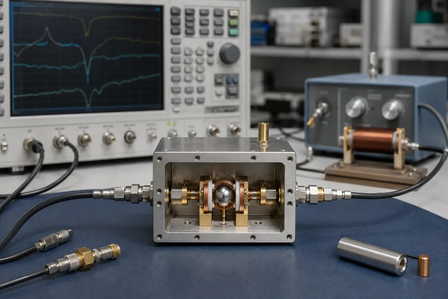
A YIG-tuned oscillator pairs an active negative-resistance device with a YIG sphere acting as the frequency-determining resonator. An electromagnet sets the sphere's resonant frequency, so the oscillator follows the coil current rather than a varactor voltage. A main coil provides coarse, wide, highly linear tuning; a small FM coil provides fast, narrow correction. Almost everything you specify — settling time, tuning linearity, hysteresis, power draw — is a property of that magnetic circuit and its driver, not of the crystal.
Key takeaways
- The resonator sets frequency; the active device only supplies gain and negative resistance.
- The main coil tunes wide and slow; the FM coil tunes narrow and fast.
- Tuning current, not tuning voltage, is the control variable.
- Hysteresis and drift come from the magnetic circuit, so calibration is part of the design.
The YIG technology section starts with what YIG is, where the resonator is the easy half. This page is the rest of the device.
The oscillator loop
An oscillator needs gain, a frequency-selective element, and a feedback path that sustains oscillation at one frequency and not others. In a YIG-tuned oscillator (YTO):
- The active device — usually a bipolar transistor at lower frequencies, a FET or HBT higher up — presents a negative resistance across the coupling structure.
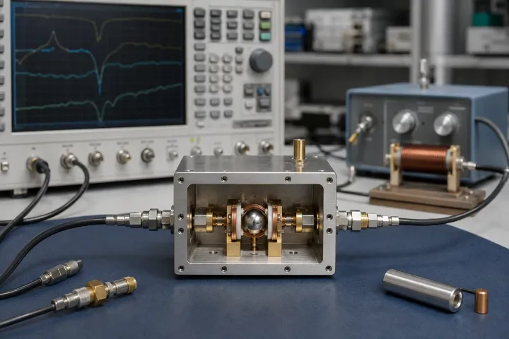
- The YIG sphere is the frequency-determining resonator, coupled through a small loop.
- The magnetic circuit sets where in frequency that resonator sits.
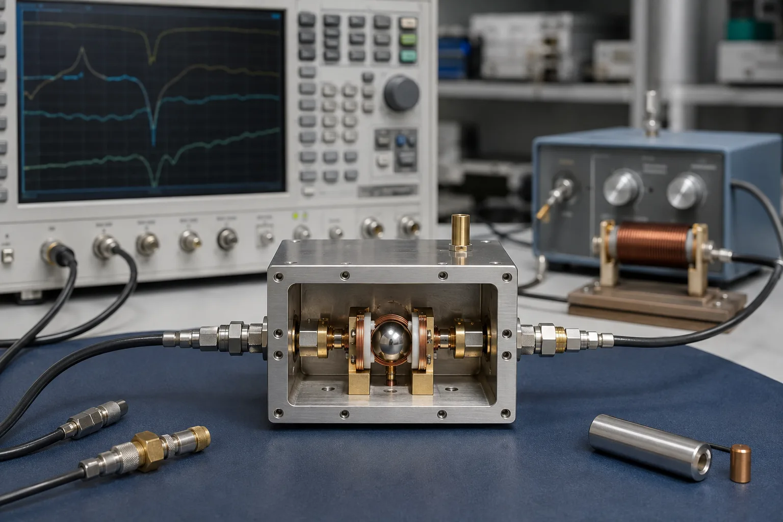
The active device does not set the frequency. It supplies enough negative resistance to cancel the resonator’s losses across the intended band, and the resonator decides where the loop oscillates. That division is why YTO phase noise tracks resonator Q so directly.
Two coils, two jobs
Practically every YTO has two tuning inputs, and confusing them is the most common integration mistake.
The main coil carries the bulk of the tuning field. It has many turns, so it tunes across the full band, and its inductance makes it slow. It is the coarse, wide, highly linear control.
The FM coil is a small auxiliary winding covering a narrow range around wherever the main coil has parked the oscillator. Fewer turns means far lower inductance, which means it responds fast enough to sit inside a phase-locked loop.
The usual arrangement follows from that: the main coil sets the operating point, and the loop drives the FM coil to correct it. Asking the main coil to do fast correction, or the FM coil to cover the band, both fail for the same reason.
This split is the first thing to check when a YTO does not behave as expected in a loop. A loop that is too slow is often a loop wired to the wrong coil.
Why the control variable is current
A varactor-tuned VCO is a voltage-controlled device. A YTO is not. Frequency follows the magnetic field, the field follows the coil current, so the oscillator follows current. The driver is therefore a current source, and its accuracy, noise and thermal behaviour land directly on the output frequency. When that distinction is the whole decision, see YIG oscillator vs VCO vs DRO.
This is why YIG oscillators are so often bought with a driver rather than bare. The driver is not an accessory; it is half of the specification.
Three driver properties land straight on the output:
- Current accuracy and resolution set how finely you can place the frequency, and therefore the size of the correction the loop must make.
- Driver noise modulates the tuning field, which modulates the frequency. Coil-current noise appears as phase noise, so a quiet oscillator behind a noisy driver is not a quiet source.
- Thermal behaviour of the driver adds to the thermal behaviour of the coil. Both drift, and they do not necessarily drift in the same direction.
A datasheet phase noise figure is measured with a specified driver. Substituting your own means the figure no longer describes what you built — see understanding phase noise for which parts of the curve a noisy tuning input tends to spoil.
What limits the tuning
Three effects dominate, and all three are magnetic rather than crystalline.
Settling time. Changing frequency means changing current through an inductive coil against its own back-EMF. Wide steps on the main coil settle in milliseconds; small steps on the FM coil are far quicker.
Hysteresis. The magnetic circuit remembers where it has been. Arriving at a frequency from below does not land in exactly the same place as arriving from above. Systems that care about absolute accuracy approach from a consistent direction, or calibrate and correct.
Thermal drift. Coil resistance and magnetic properties both move with temperature, so a fixed current does not mean a fixed frequency across the operating range. Manufacturers offer standard and extended temperature grades — commonly 0 to +65 °C standard, with −20 to +70 °C and −40 to +85 °C options — and the grade you pick changes the correction you have to do downstream.
Specifying the magnetic circuit
| Property | Set by | Downstream consequence |
|---|---|---|
| Settling time | Coil inductance and driver compliance | Maximum sweep or hop rate |
| Tuning linearity | Magnet geometry and field uniformity | Size of the correction table |
| Hysteresis | Magnetic history of the circuit | Absolute accuracy without recalibration |
| Thermal drift | Coil resistance and magnetic temperature coefficients | Whether you need active temperature correction |
| Standby power | Coil current needed to hold frequency | Thermal design and supply budget |
| External field sensitivity | Shielding and physical layout | Mechanical clearance rules in the enclosure |
These are properties of the magnet and its driver, not of the YIG crystal. Swapping the resonator changes none of them.
What you get for it
Commercial electromagnet YTOs span roughly 700 MHz to 40 GHz across the product range, with output levels around +9 to +17 dBm and phase noise at 100 kHz offset in the region of −123 to −130 dBc/Hz on the quieter models, per the manufacturer’s published tables.
Whether those numbers are good depends entirely on the offset you care about, which is the subject of the phase noise guide. For selection criteria and the full parameter list, see the YIG oscillator component guide, and for the material behind the resonator, what YIG is.
Common integration mistakes
- Driving the main coil from a voltage source. Frequency follows current. A voltage drive makes coil resistance — which moves with temperature — part of your frequency control.
- Closing the loop on the main coil. It will be too slow, and the fix is not more loop gain.
- Measuring settling with the wrong step size. A full-band settling figure says nothing about a 10 MHz correction, and the reverse is equally true.
- Ignoring approach direction. Hysteresis means arriving from above and from below give different answers. Pick one and be consistent, or calibrate for both.
- Leaving magnetic clearance to the mechanical phase. By then the enclosure is fixed and the transformer is already next to the oscillator.
Where the oscillator sits relative to mixers and filters is covered in RF, IF and LO explained.
A tuning procedure is part of the architecture
The useful abstraction is not “a YTO tunes with current,” but a chain of control actions. A stored calibration maps requested frequency to a main-coil current. The main current moves the magnetic field close to the destination. A faster correction path, usually through the FM coil and a phase detector, removes the residual frequency error. The loop therefore has three separate questions: how close the table gets, how fast the magnet can move, and how much correction authority remains after it arrives.
Approach direction has to be defined before calibration data is collected. A magnetic circuit retains some history, so the same nominal main-coil current can produce slightly different frequencies after an upward sweep and a downward sweep. A practical system either always approaches the operating point from one direction, includes a deliberate overshoot and return, or stores direction-specific corrections. Calling this “hysteresis compensation” without documenting the movement rule leaves a repair technician with an unrepeatable instrument.
The driver is likewise part of the RF design. Its current noise is frequency modulation, its voltage compliance sets how quickly current can change in an inductive coil, and its thermal drift changes the calibration that was valid at room temperature. A low-noise current source can still be a poor choice if it cannot supply the voltage needed for the required step. Conversely, a fast driver that adds noise to the tuning port can spoil the phase-noise advantage that justified a YIG source. Read its contribution alongside the phase-noise budget, not as a separate power-supply specification.
Acceptance testing should follow this architecture. Test absolute frequency after a controlled approach, repeat it at the operating temperature limits, and measure settling to the error band the receiver or transmitter can actually tolerate. Test lock recovery after reference removal if the source is used in a PLL. These checks turn a broad tuning range into a predictable, maintainable LO rather than a promising bench oscillator.
Frequently asked questions
Why two coils?
One coil cannot be both wide and fast. The main coil has many turns for wide tuning, which makes it inductive and slow; the FM coil has few turns over a narrow range, which makes it fast enough for phase-lock correction.
Can a YIG oscillator be phase-locked?
Yes, and it usually is. The loop normally drives the FM coil, with the main coil setting the coarse operating point.
Does it need calibration?
In practice yes. The current-to-frequency relationship is highly linear but not perfectly repeatable across temperature and magnetic history, so systems typically calibrate and then correct.
Sources
- Electromagnetic YIG Oscillators (Wide Tuning Range) — Micro Lambda Wireless Accessed August 28, 2026.
- Phase Noise Measurements with a Real-Time Spectrum Analyzer, chapter 7 — Berkeley Nucleonics Accessed August 28, 2026.