Direct answer
Use a YIG-tuned filter when the passband must move across an octave or more and remain a roughly constant absolute width. Use a cavity filter when the band is fixed, insertion loss and power handling matter more than tunability, and you can accept a bandwidth that is a percentage of centre frequency. A switched cavity bank is the third option when you need both low loss and several discrete bands — it is not a faster YIG filter. Electrical tuning and cavity Q are different purchases; one driver will not turn either part into the other.
Key takeaways
- YIG buys a moving, near-constant absolute bandwidth; a cavity buys Q at one frequency.
- A YIG preselector costs real insertion loss where a cavity costs little; the gap widens with stage count.
- A cavity’s width scales with centre frequency; a YIG’s width does not, except for a ~20% creep per octave.
- If the frequency plan is a short list of channels, a switched bank usually beats both extremes.
- Sphere limiting around 0 to +10 dBm rules a YIG filter out of high-power paths.
A filter comparison that starts with Q-factor is already answering the wrong question. The useful split is whether the passband has to move. If it does, and it must stay tens of megahertz wide across an octave, the part is a YIG-tuned filter. If it does not, the part is almost always a cavity. That is the decision this page is for; the rest of the YIG technology section is the mechanism.
The conclusion
Use a YIG-tuned filter as a tracking preselector — in a spectrum analyser, a wideband EW or monitoring receiver, or any front end whose LO walks a multi-octave band. You are buying a moving, near-constant absolute bandwidth. You are paying 4 to 12 dB of insertion loss, millisecond settling, coil power and a magnet.
Use a cavity filter on a fixed channel — a SATCOM transponder, a radar on a known frequency, a base-station duplex path, a high-power transmitter. You are buying the higher unloaded Q of a machined resonator and the low insertion loss that can sit between 0.2 and 2 dB. You are giving up electrical tuning.
Use a switched cavity bank when the frequency plan is a short list. That is the honest way to combine low loss with more than one band. It is not a YIG filter with extra switches, and it will not cover the spaces between the cavities.
What each one actually is
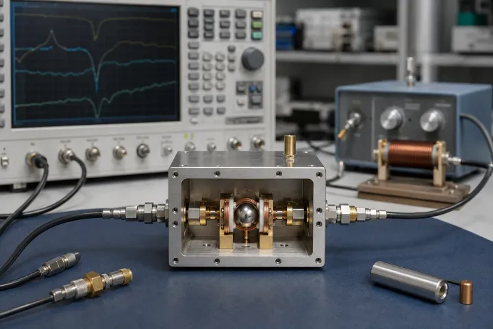
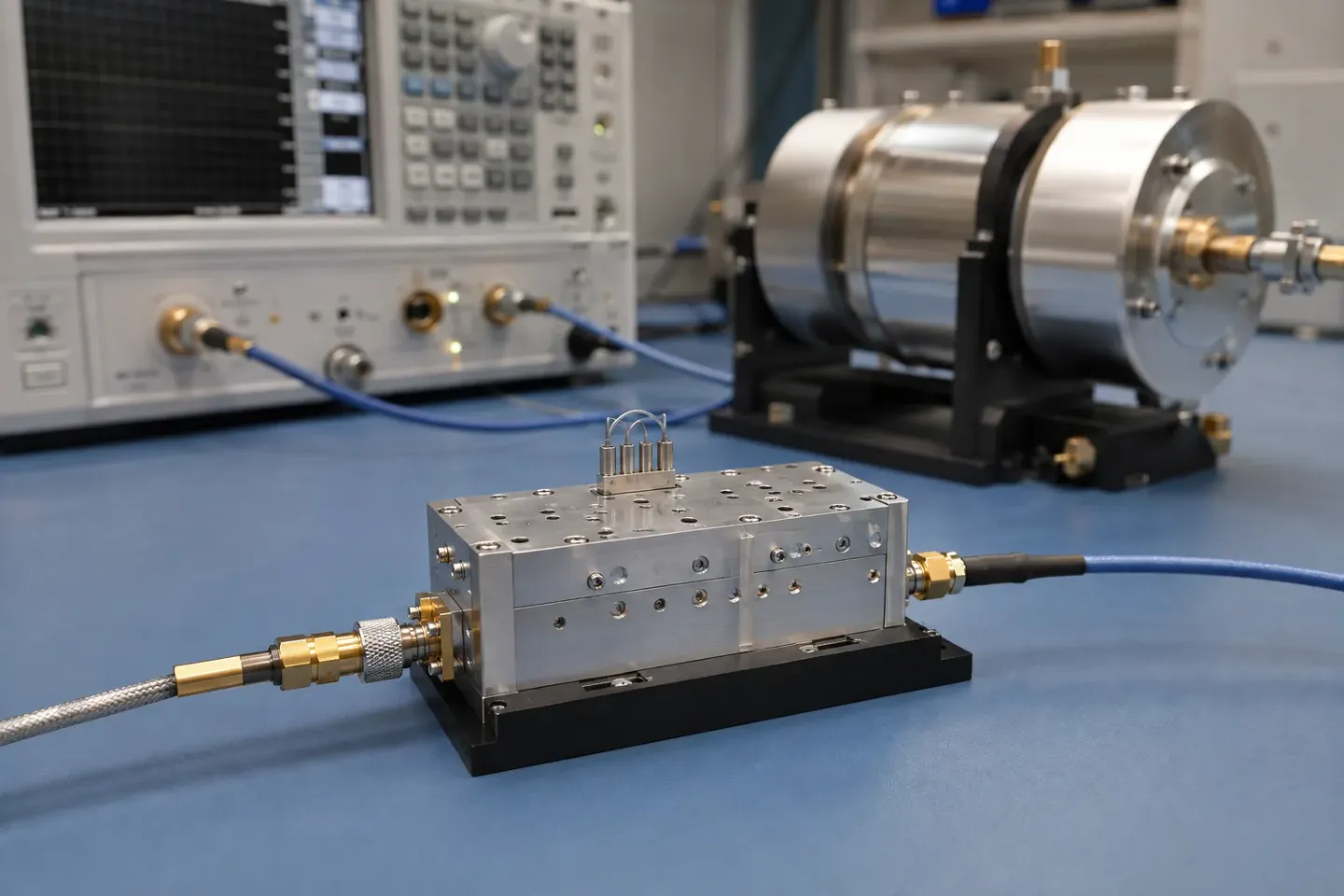
A YIG filter couples one or more spheres to small loops and moves their common resonance with an electromagnet. Bandwidth is a function of loop spacing and stage count. Frequency is a function of coil current. What YIG is is the material reason that works at all.
A cavity filter is a machined resonance. Coaxial cavities typically land in the 1,000 to 5,000 unloaded-Q region; waveguide cavities reach 5,000 to 20,000, with lower loss and higher power, at the cost of size. Waveguide is the high-power, high-frequency choice; coaxial is the compact one below about 18 GHz. Neither follows a coil current across an octave.
Side by side
| Criterion | YIG-tuned filter | Cavity filter | Switched cavity bank |
|---|---|---|---|
| How the band moves | Coil current, octave or more | Screws, or not at all | A switch chooses a cavity |
| Bandwidth shape | Absolute width; ~20% creep per octave | Percentage of a fixed centre | Percentage, per selected cavity |
| Unloaded Q | High for a ferrite; not cavity-Q | 1,000–20,000 | 1,000–20,000 per path |
| Insertion loss | 1–3 dB published for the class; rises with stage count | Sub-dB in waveguide at 10 GHz | Cavity loss plus the switch |
| Selectivity control | Add spheres | Add poles; each costs loss and volume | Add poles on the bands you built |
| Power handling | Sphere limiting ~0 to +10 dBm | Tens to hundreds of watts in waveguide | Per-path cavity rating |
| Settling | Milliseconds | None once aligned | Switch time |
| SWaP | Magnet and coil current | Machined metal, no coil | Several cavities plus switches |
| Typical role | Tracking preselector | Fixed channel, high power | A known list of bands |
The published figures are 1 to 3 dB for a YIG preselector and about 0.3 dB for a waveguide cavity at 10 GHz, against 1.5 dB for a microstrip equivalent. Read the YIG figure as the low-stage-count end: adding stages buys skirt steepness and costs loss, so a high-order part sits well above it. These are class envelopes, not a promise that any given part sits at the pretty end. A six-stage 2–18 GHz YIG filter and a four-pole coaxial cavity at 2 GHz with 5% bandwidth are both “filters” and almost never compete for the same slot.
Why the bandwidth shape matters
A 30 MHz YIG passband at 2 GHz is a 1.5% filter. The same 30 MHz at 18 GHz is 0.17%. That is the property a wideband receiver is buying: the preselector does not open as the LO climbs. A cavity specified as 2% wide would be 40 MHz at 2 GHz and 360 MHz at 18 GHz — which is why nobody specifies a single cavity across that span.
The published YIG correction is the ~20% expansion per octave. It is real, and it is still an order of magnitude smaller than percentage scaling. Specify the width at the top of the tune.
Image rejection is a filter decision
The reason a receiver has a preselector at all is the image: a second RF, 2 × IF from the wanted signal, that the mixer cannot tell apart. RF, IF and LO is the frequency-plan version. The hardware version is this page.
- If the LO walks a wide band, only a filter that walks with it can keep the image out. That is a YIG filter, or a bank with as many cavities as you have tune positions — which is to say, a YIG filter by another name and a worse parts count.
- If the RF is a fixed channel, a cavity (or a fixed ceramic, SAW or waveguide filter) can sit on the image offset permanently, at much lower loss.
Insertion loss ahead of the first gain stage adds directly to noise figure. A 6 dB YIG preselector in front of the LNA is a 6 dB noise-figure purchase. Put the same filter after the LNA and you spend linearity and recovery instead. Neither placement is free; the cavity’s lower loss is why fixed-channel radios almost never use YIG here.
What to pick, by job
- Analyser, EW receiver, monitoring front end. YIG. Coverage binds. Pair it with the YIG oscillator and budget settling once, together.
- SATCOM channel, radar on a known frequency, transmitter harmonic filter. Cavity. Loss and power bind. Waveguide if the power or the frequency says so.
- A radio with six known bands. Switched bank. Do not buy a YIG filter and then only ever park it on six currents.
- Radar that must tune. Split the problem. The tracking piece can be YIG; the high-power piece on the transmit side stays a cavity. See radar RF components.
The same three-way split — wide-and-slow, agile-and-noisier, fixed-and-quiet — is the oscillator comparison written for sources rather than filters. If you are pairing a YTO with a YIG preselector, read both before you budget settling.
Write the blocker scenario first
Filter choice becomes much clearer when it starts with a specific unwanted signal. State the wanted RF range, the IF, the resulting image location, the largest unwanted level and the amount of rejection required before the first mixer. If the wanted frequency sweeps continuously, that image moves with it; a single fixed cavity cannot remain at the right offset. A tracking YIG filter can, provided its bandwidth, calibration and settling time are included in the same plan as the LO.
For a fixed channel, make the opposite calculation. A cavity can be centred where the unwanted energy is most troublesome and can often deliver lower loss, greater power capability and sharper fixed rejection. There is no prize for continuous tuning that the system never uses. If the service occupies a modest list of channels, compare a switched bank honestly: include switch loss, switching time, calibration and the number of filters, rather than assuming a tunable part is automatically simpler.
Bandwidth needs an absolute unit before it can guide the decision. A tracking preselector must pass the desired signal under temperature and tuning error while attenuating the blocker at the image offset. A filter that is too narrow clips modulation or turns frequency error into amplitude variation; one that is too wide provides little protection. Determine the passband and rejection at the top and bottom of the operating range, where a YIG filter’s bandwidth behaviour may not look like one mid-band number.
Placement changes the trade as well. Before the LNA, insertion loss raises receiver noise figure but shields the LNA and mixer from blockers. After the LNA, noise performance improves but the amplifier must remain linear in the blocker environment. A cavity and a YIG filter may therefore be evaluated at different points in the same receiver. Coordinate this with the RF, IF and LO plan so the filter is selected for the product it actually needs to reject.
Acceptance should include a moving test for a moving filter: tune across the band, inject desired and image-like signals at each point, and record loss, isolation and settling after representative steps. A static plot at one frequency proves neither tracking accuracy nor real-world protection.
Frequently asked questions
Can I tune a cavity electrically?
Not in the sense that matters here. Production cavities are aligned with screws. Some designs add a varactor or a motor; the tuning range is a sliver of what a YIG filter covers, and the Q usually falls as you pull it. Treat a cavity as fixed unless the datasheet shows otherwise.
Why is a YIG filter so much lossier?
Because the sphere and the loops are a loosely coupled, magnetically tuned resonator, not a machined metal cavity. Stage count, which is how you buy selectivity, adds loss each time. That loss is the price of moving the band.
Will a YIG filter reject a high-power interferer better?
It may reject it spectrally, then saturate. Published limiting levels for the class are 0 to +10 dBm. A cavity will typically take far more power before it stops being the filter you specified. Isolation and power handling are different specifications.
When is a switched bank the real answer?
When you have a known list of bands, need cavity-like loss, and can spend switch time instead of coil settling. Continuous coverage between those bands is what you give up.
Sources
- Key differences between RF band reject and band pass YIG filters — Micro Lambda Wireless Accessed August 28, 2026.
- How to Design a Frequency-Tunable Bandpass Filter Using YIG Resonators — RF Essentials Accessed August 28, 2026.
- Waveguide vs Coaxial Cavity Bandpass Filters — RF Essentials Accessed August 28, 2026.
- The Role of the Preselector Filter in a Receiver Front End — RF Essentials Accessed August 28, 2026.