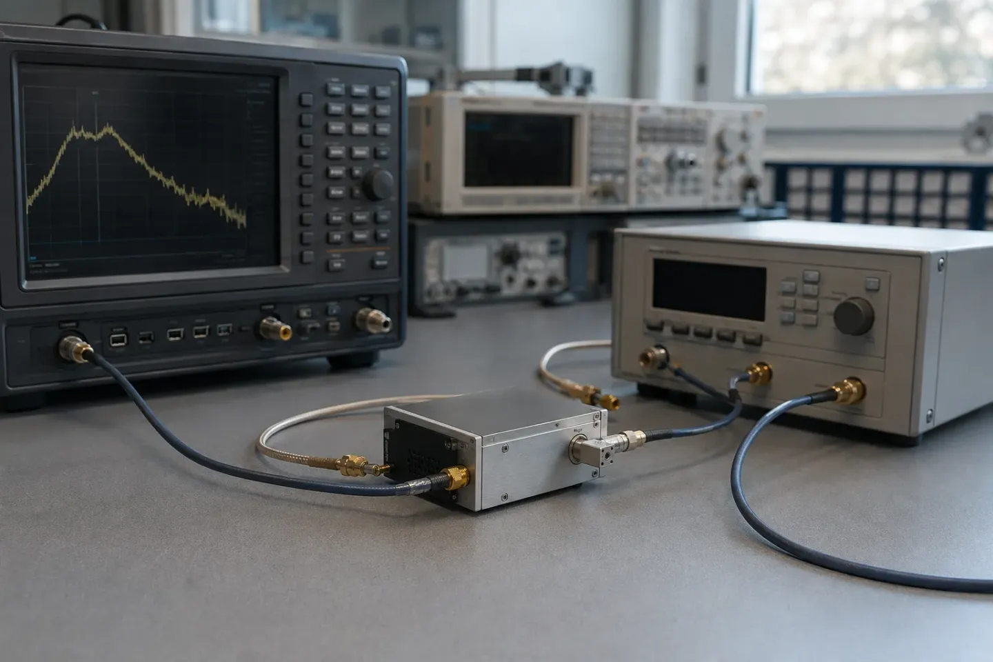
Direct answer
A microwave frequency synthesizer generates a programmable output frequency by phase-locking an oscillator to a stable reference. The loop divides the output by N and compares it against the reference at a phase-detector frequency; the loop filter then corrects the oscillator. Inside the loop bandwidth the output inherits the reference's noise, multiplied by 20·log(N); outside it, the oscillator's own noise dominates. Choosing a synthesizer is therefore mostly choosing where to put that crossover, and what to give up — resolution, lock time or spurious content — to put it there.
Key takeaways
- The loop bandwidth decides which noise source you inherit at which offset.
- Division by N multiplies reference phase noise by 20·log(N).
- Integer-N ties step size to the phase-detector frequency; fractional-N breaks that link and pays in spurs.
- With a YIG oscillator as the VCO, the loop drives the FM coil while the main coil parks the band.
- Lock time and spurious performance both trade against loop bandwidth, in opposite directions.
A frequency synthesizer turns one accurate frequency into any of many programmable ones. A stable reference — usually an oven-controlled or temperature-compensated crystal — feeds a phase detector. The oscillator’s output is divided by N and compared against that reference; the difference, filtered, steers the oscillator until the two agree. The output is then N times the comparison frequency, and it inherits the reference’s long-term accuracy. What it inherits in short-term noise depends entirely on where the loop bandwidth sits, and that is the decision the whole specification turns on.
Where it sits in the chain
A synthesizer is a frequency source with a programmable output. In a receiver it is the local oscillator; in a transmitter, the exciter; in test equipment, the signal source. Everything downstream — the mixer or converter, the IF chain — inherits its phase noise and its spurious content, which is why the synthesizer specification tends to bound system performance rather than merely contribute to it.
The loop
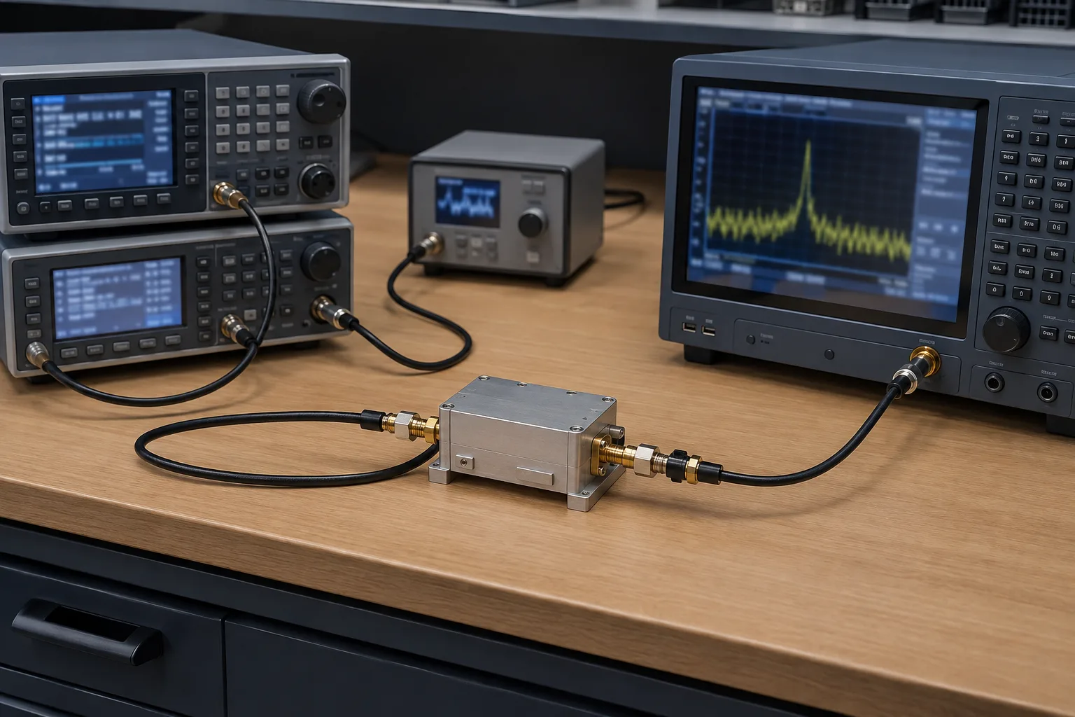
Four elements, and each one owns a specification you will later argue about.
The reference sets long-term accuracy and drift, and its phase noise is what the output carries close to the carrier. An OCXO is quieter and more stable than a TCXO, larger, and needs warm-up.
The phase detector compares at a frequency f_PD. Its own noise floor, multiplied up by the division ratio, sets the close-in floor of the whole synthesizer.
The loop filter sets the loop bandwidth, and therefore the crossover between the two noise regimes. This is the single most consequential design choice in the loop.
The oscillator — the VCO in the general case, a YIG oscillator in wideband microwave designs — contributes the noise outside the loop bandwidth.
The two relationships worth internalising
Division multiplies reference noise. The loop forces the output to track N times the reference, so the reference’s phase deviation is multiplied along with its frequency: a 20·log(N) penalty in decibels. A division ratio of 1,000 costs 60 dB. This is why large N is expensive, and why architectures work hard to keep it small.
Loop bandwidth chooses your noise source. Inside the loop bandwidth the output tracks the reference, so you get reference noise plus 20·log(N). Outside it, the loop no longer corrects fast enough and you get the oscillator’s own noise. A wide loop pulls more of the curve down to the reference — good, if the reference is quiet and N is small. A narrow loop leaves more of the curve to the oscillator — good, if the oscillator is a low-noise YIG source.
There is no universally correct answer, which is why reading the phase noise plot matters more than reading a single number. Ask which offsets your system integrates over, then ask where this synthesizer’s crossover sits relative to them.
Architectures
| Criterion | Integer-N | Fractional-N | Multi-loop | Direct digital (DDS) hybrid |
|---|---|---|---|---|
| Step size | Equal to f_PD | Fraction of f_PD | Fine, via a second loop | Very fine |
| Division ratio N | Large for fine steps | Smaller for the same step | Small in each loop | Small |
| Close-in phase noise | Degrades with fine steps | Better for the same step | Good | Good |
| Spurious content | Reference spurs at f_PD multiples | Adds fractional spurs | Loop interaction spurs | DDS spurs across the band |
| Lock time | Limited by f_PD | Faster for the same step | Depends on the slowest loop | Fast |
| Complexity | Lowest | Moderate | High | High |
The pattern behind that table: integer-N ties step size to the comparison frequency, and everything else follows from that constraint. Fine steps mean a low f_PD, which means a large N, which means a 20·log(N) noise penalty and a slow loop. Fractional-N breaks the tie by dividing by a non-integer on average, allowing a higher f_PD for the same step — and pays for it with spurs generated by the division sequence itself.
Reference spurs sit at multiples of the comparison frequency, which at least makes them predictable. Fractional spurs are less obliging, and suppressing them is where much of the engineering in a modern fractional-N part goes.
When the VCO is a YIG oscillator
Microwave synthesizers covering an octave or more usually use a YIG oscillator as the loop VCO, and that changes three things.
The loop drives the FM coil, not the main coil. The main coil parks the oscillator near the target; the loop corrects from there through the fast, narrow FM winding. The mechanism is in how YIG oscillators work.
Lock time gains a magnetic term. Before the loop can capture, the main coil has to settle — a millisecond-scale magnetic process, not a loop-bandwidth one. Quoted lock times should say whether they include that.
Noise outside the loop is unusually good. That is the whole reason to accept the size and power. Commercial electromagnet YIG oscillators reach −123 to −130 dBc/Hz at 100 kHz offset on quieter models, across tuning ranges spanning roughly 700 MHz to 40 GHz — which is what lets one loop cover a band that would otherwise need several.
Key specifications
| Parameter | What it means | What it constrains |
|---|---|---|
| Frequency range | Span of programmable output | How many sources the frequency plan needs |
| Step size / resolution | Smallest programmable increment | Channel plan; and, in integer-N, everything else |
| Phase noise | ℒ(f) at stated offsets, locked | Receiver reciprocal mixing and achievable noise figure |
| Spurious | Discrete tones, reference and fractional | Spurious responses — these do not integrate like noise |
| Lock / switching time | Time to settle within tolerance after a command | Hop rate; sweep rate; test throughput |
| Reference input | External 10 MHz in, or internal OCXO/TCXO | System coherence and long-term accuracy |
| Harmonics | Output multiples of the carrier | Filtering needed ahead of a broadband mixer |
Parameter meanings are general to the device class. Values vary by architecture and vendor; work from the specific part's datasheet.
Two of those deserve emphasis because they are routinely conflated.
Spurious is not phase noise. A spur is a deterministic tone. It does not integrate the way broadband noise does, and one spur landing in a critical offset can matter more than several decibels of clean noise elsewhere.
Lock time is not one number. Time to reach a coarse tolerance and time to settle to a tight one can differ by an order of magnitude, and with a YIG-based source the magnetic settling may or may not be included. Ask what tolerance the quoted figure refers to.
Selection criteria
Advantages and limitations
Advantages. Programmable frequency with the reference’s long-term accuracy. Predictable noise behaviour once the loop bandwidth is known. With a YIG VCO, a single unit covering an octave or more at genuinely low noise.
Limitations. Every architecture trades resolution, lock time and spurs against each other; none of the three is free. Reference quality bounds close-in performance no matter what the oscillator does. YIG-based units inherit the size, power draw and magnetic sensitivity of a magnetically tuned source.
Typical applications
Receiver and exciter local oscillators in radar, electronic warfare and SIGINT, where wide coverage and low reciprocal mixing both matter. Automated test equipment, where switching time drives throughput. SATCOM up- and downconverters, where long-term stability and coherence dominate. Spectrum monitoring, where the synthesizer and a tracking preselector must be budgeted together — a preselector’s 1 to 3 dB insertion loss lands directly on system noise figure, so the LO has to be good enough to justify it.
Testing and integration notes
- Measure phase noise locked, on the assembly you will ship, at the carrier you will use.
- Characterise lock time to your tolerance, not the datasheet’s, and from the worst-case frequency step.
- Sweep for spurs across the whole output band, not only near the carrier. Reference spurs are predictable; fractional spurs are not.
- Verify behaviour on an external reference if the system uses one, including reference loss and reacquisition.
- Budget warm-up if an OCXO is inside — specifications rarely hold at power-on.
Related guides
- YIG oscillators — the wideband VCO these loops are usually built around
- How YIG oscillators work — why the loop drives the FM coil
- Understanding phase noise — reading ℒ(f) rather than a headline figure
- RF signal chain — where a source sits relative to mixers and filters
- Component sourcing and quality — obsolescence and traceability on long-life parts
Specify the transition, not only the settled frequency
Two synthesizers can both reach the same carrier with the same nominal resolution and still behave very differently in a system. The difference appears during a frequency change. A PLL must move the controlled oscillator, reacquire phase, let any reference-related transients decay and meet the output tolerance that the next stage actually needs. “Lock” is not a universal end state: a spectrum analyser may accept a small residual error while it waits for a filter to settle, whereas a coherent radar exciter may need phase repeatability before the next pulse.
Write the transition as a testable requirement. State the start and stop frequencies, the direction, the requested time, the final frequency error, the allowed residual FM and whether output should be blanked while the loop moves. If a tracking preselector shares the sweep, include its current command and settling interval in the same timeline. This brings the source and filter decision back to the YIG filter guide rather than treating them as unrelated catalog items.
The noise specification also needs a reference plane. Inside the loop bandwidth, the output commonly follows the reference and divider noise; outside it, the controlled oscillator dominates. A quiet free-running YIG element does not automatically yield a quiet locked assembly, and a low-noise reference does not repair a noisy tuning path. Ask for a plot at the carrier and offsets that matter to the receiver, then read it with the phase-noise guide before comparing architectures.
For production, capture the external-reference case as well as the internal-reference case. A unit that is stable on its own oscillator but slow to reacquire a system reference is not interchangeable in a coherent installation. Include warm-up state, reference level and switching history in the test record so that a later replacement can be evaluated under the same conditions.
Frequently asked questions
Why does frequency division degrade phase noise?
Inside the loop the output is forced to track N times the reference, so the reference's phase deviation is multiplied by N along with its frequency. In decibels that is a 20·log(N) penalty, which is why large division ratios are expensive in noise terms.
What sets the lock time?
Principally the loop bandwidth — a wider loop corrects faster. With a YIG oscillator there is a second term, because the main coil has to move the oscillator into the loop's capture range first, and that is a magnetic settling time rather than a loop time.
Where do reference spurs come from?
The phase detector operates at a discrete comparison frequency, and imperfect suppression of that process leaves discrete tones at multiples of it. Fractional-N adds its own spurs from the division sequence, which is the price of decoupling step size from the comparison frequency.
Why use a YIG oscillator rather than a varactor VCO in the loop?
For wide coverage with low noise outside the loop bandwidth. A YIG oscillator covers an octave or more at low phase noise, so one loop replaces several. Where the requirement is fast switching over a narrow span, a varactor VCO is the better VCO.
Sources
- Electromagnetic YIG Oscillators (Wide Tuning Range) — Micro Lambda Wireless Accessed August 28, 2026.
- Phase Noise Measurements with a Real-Time Spectrum Analyzer, chapter 7 — Berkeley Nucleonics Accessed August 28, 2026.
- The Role of the Preselector Filter in a Receiver Front End — RF Essentials Accessed August 28, 2026.